Oliver Palmer
E-Bike Build
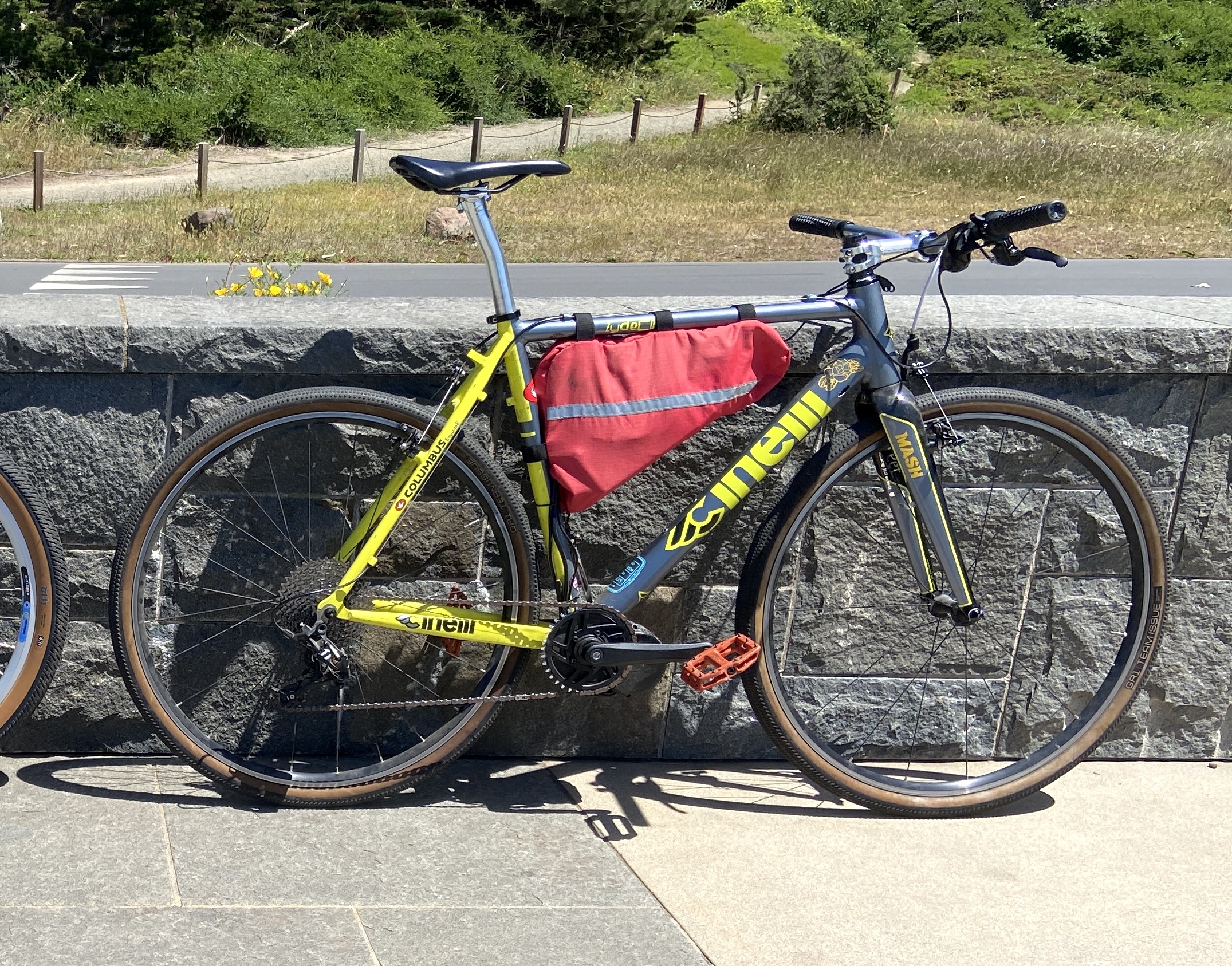
I converted my old Cinelli Zydeco cyclocross bike into a mid drive e-bike with a custom battery pack.
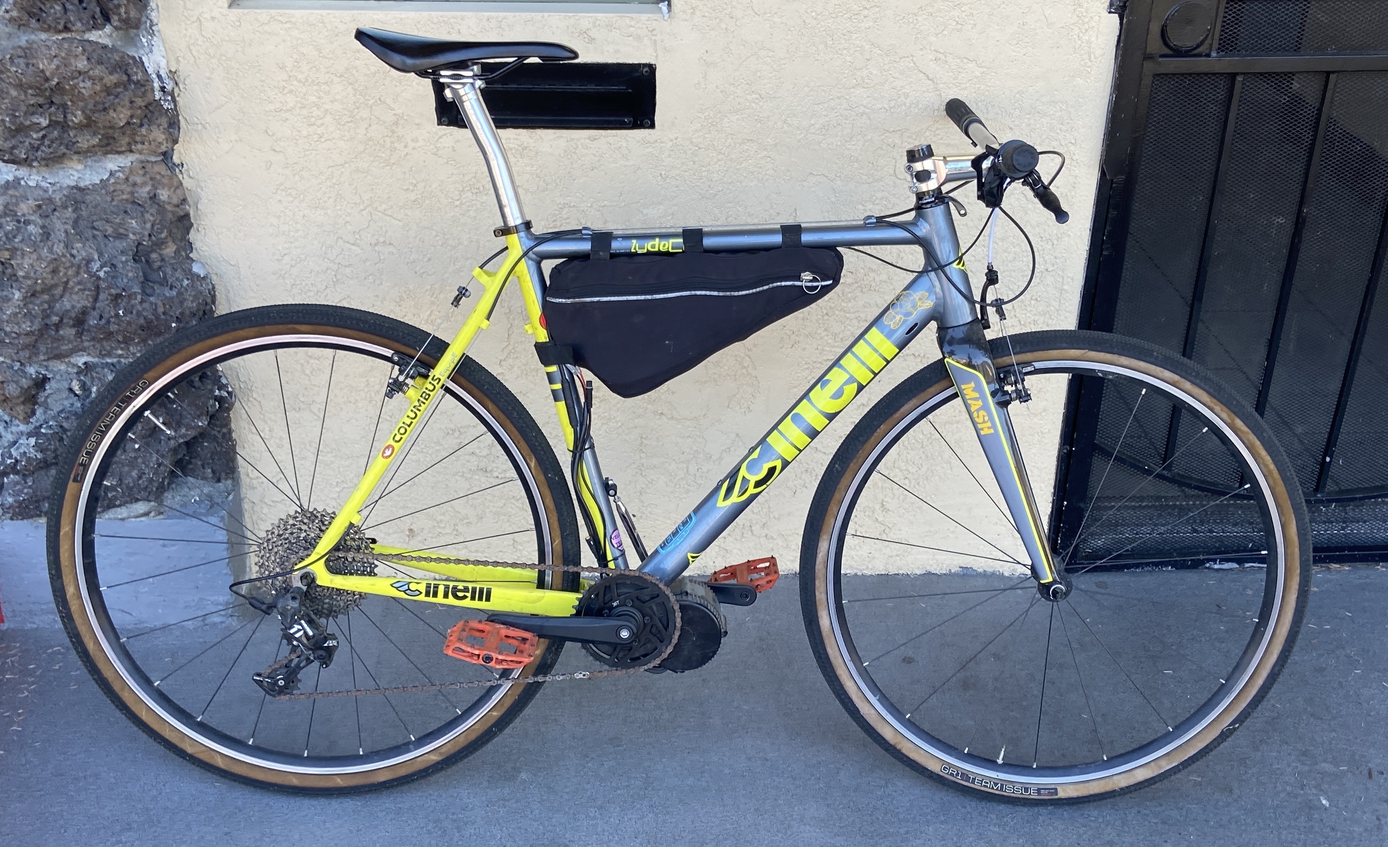
Once I started looking into the details of e-bike conversions, I realized I could get some more use out of my old bike and at the same time learn how to make a battery from individual lithium ion cells. I liked the look of mid drive motors as well, which I hadn't realized were an option for conversions; I had only seen the bulky hub drive motors in rear wheels before.

The Bafang BBS series motors seem to be the most popular choice for mid drive motor conversions nowadays. I went with the 48V 750W BBS02 model. The motor assembly contains the motor along with the motor controller/driver circuitry, so all that is needed externally is a 48V battery pack and a display module for changing the power assist levels while riding. The display talks to the motor controller over a 3.3V UART connection, and can enable or disable the motor through a dedicated "power lock" signal wire. Wanting to keep with a subtle install, I connected the UART wires to a USB-serial adapter and the power lock wire to the positive connector wire through an on/off rocker switch. The serial adapter and on/off switch fit inside a small 3D printed case tucked within the frame bag. Since I just intended to use the bike with the throttle and wouldn't need to change pedal assist modes while riding, I set the motor controller settings with a computer using the open source BafangWebConfig tool.
With the motor installed in the frame and the controls sorted, I needed to build the 48V battery pack. This nominal 48 volts refers to a battery of 13 lithium ion cells in series, since each cell has a nominal/average voltage of 3.7V based on the discharge curve. The cells have a fully charged voltage of 4.2V, so the entire 13S battery will actually be recharged to around 54V at full capacity. The BBS02 motor has a nominal power rating of 750W (~15A), but the motor controller current limit can be set as high as 25A for an output of ~1200W.
I decided to go with 21700-sized Molicel P42A cells, rated for 45A continuous discharge with a capacity of 4Ah.
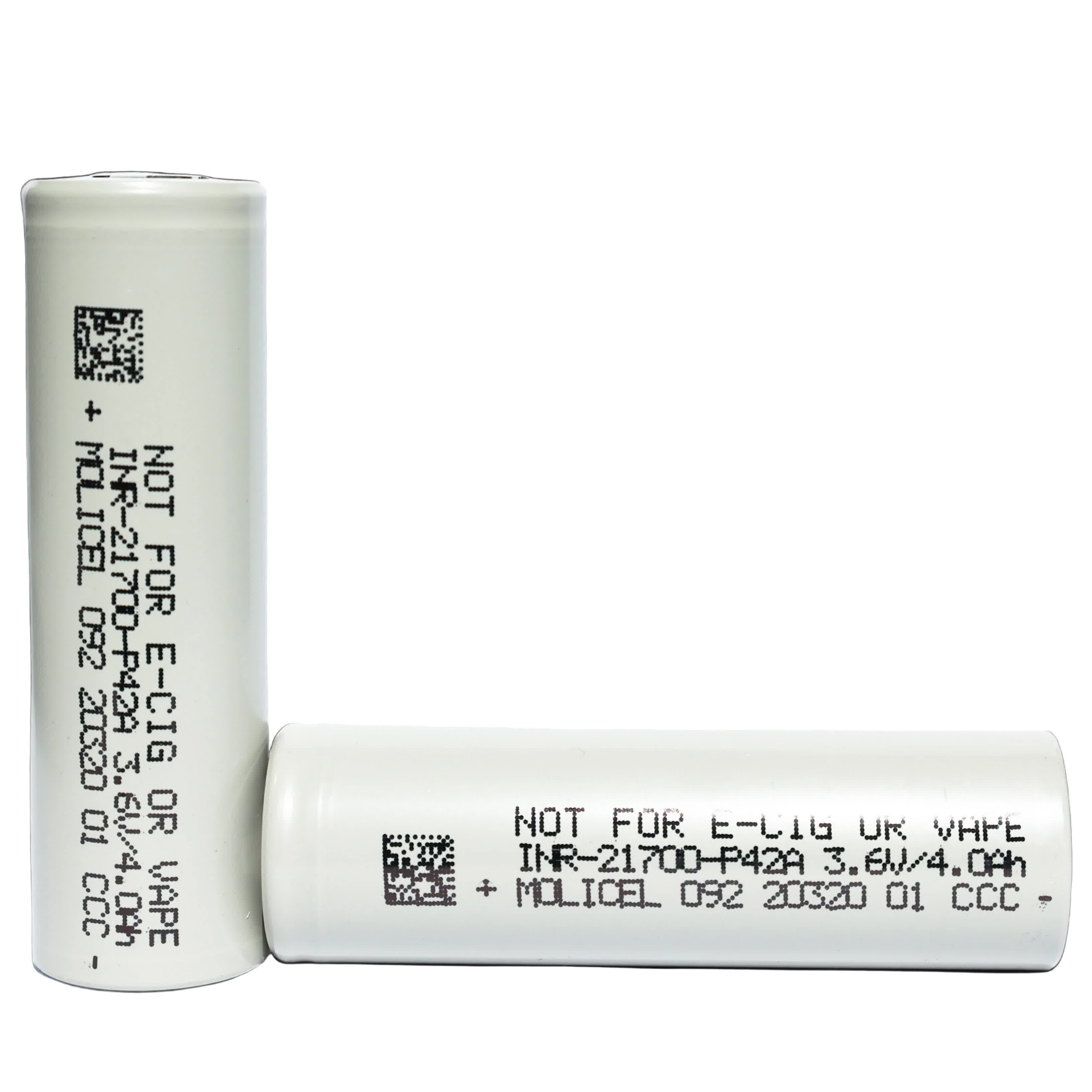
I bought 52 cells intending to make a 13S 4P battery for maximum biking range, with groups of 4 parallel cells connected at each of the 13 series positions. After feeling the weight of all 52 cells, I changed my mind and decided to construct 2 identical batteries in a 13S 2P configuration. Some online e-bike battery range calculators estimated I could get around 20 miles of range using the throttle for the 13S 2P pack, which I decided would be worth the weight savings.
The Molicel P42As are unprotected cells, like most li-ion cells available. Protection circuits are necessary for safe operation, acting as cutoffs when the cell reaches a voltage above/below an acceptable range, or exceeds a maximum specified current. On top of needing protection, the cells in a series battery pack will need individual monitoring and balancing during recharging, since individual cell capacities will vary slightly and change over time; without balancing and recharging each cell individually, certain lower capacity cells would be at risk of overcharging.
This protection and balancing in battery packs is taken care of by the battery management system, or BMS. Any li-ion battery pack for any application has a BMS for safety. For the e-bike battery, I needed a BMS for my 13S configuration with current limits above the maximum 25A of the BBS02 motor, but below the 90A limit of the 2P parallel cell groups. I went with a Daly brand 13S BMS with a current limit of 30A.
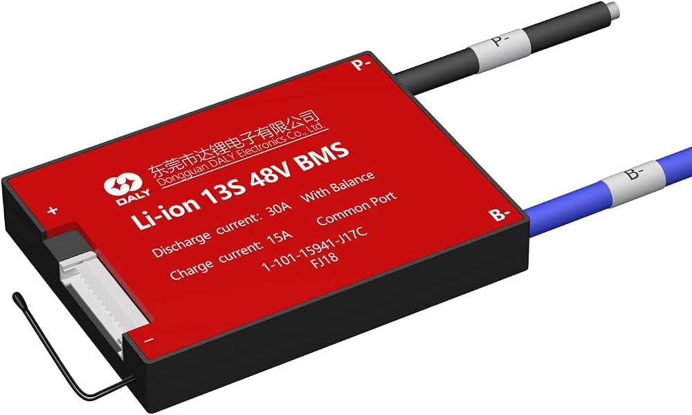
The BMS is wired between the negative terminal of the unprotected battery and the negative "power" output wire which goes to the motor connector, acting as a low side breaker. The positive terminal of the battery is wired directly to the motor connector. The BMS also has a pigtail connector with wires for balancing during recharge, with a wire for each series position in the pack.
To package the cells, I threw together a spacer/end cap model in Fusion360 for 3D printing.
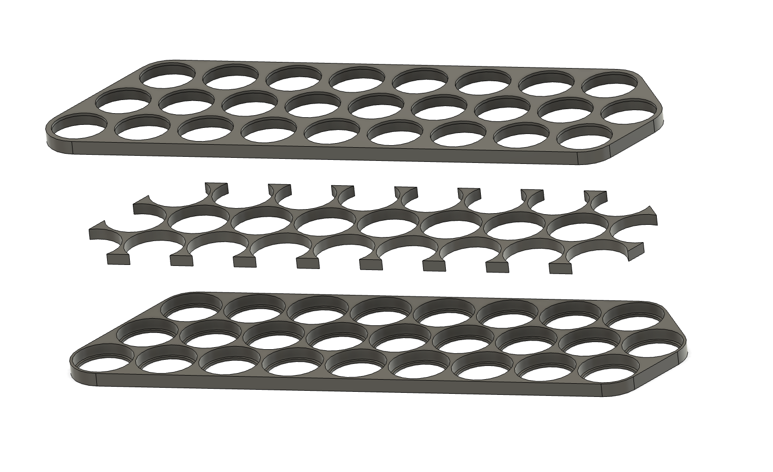
The cells would be inserted in their parallel pairs, with the orientation of each pair alternating, so that the pairs could all be spot welded together with nickel strips to form the series battery. For the spot welder, I found a portable unit for $35 which could handle the task.
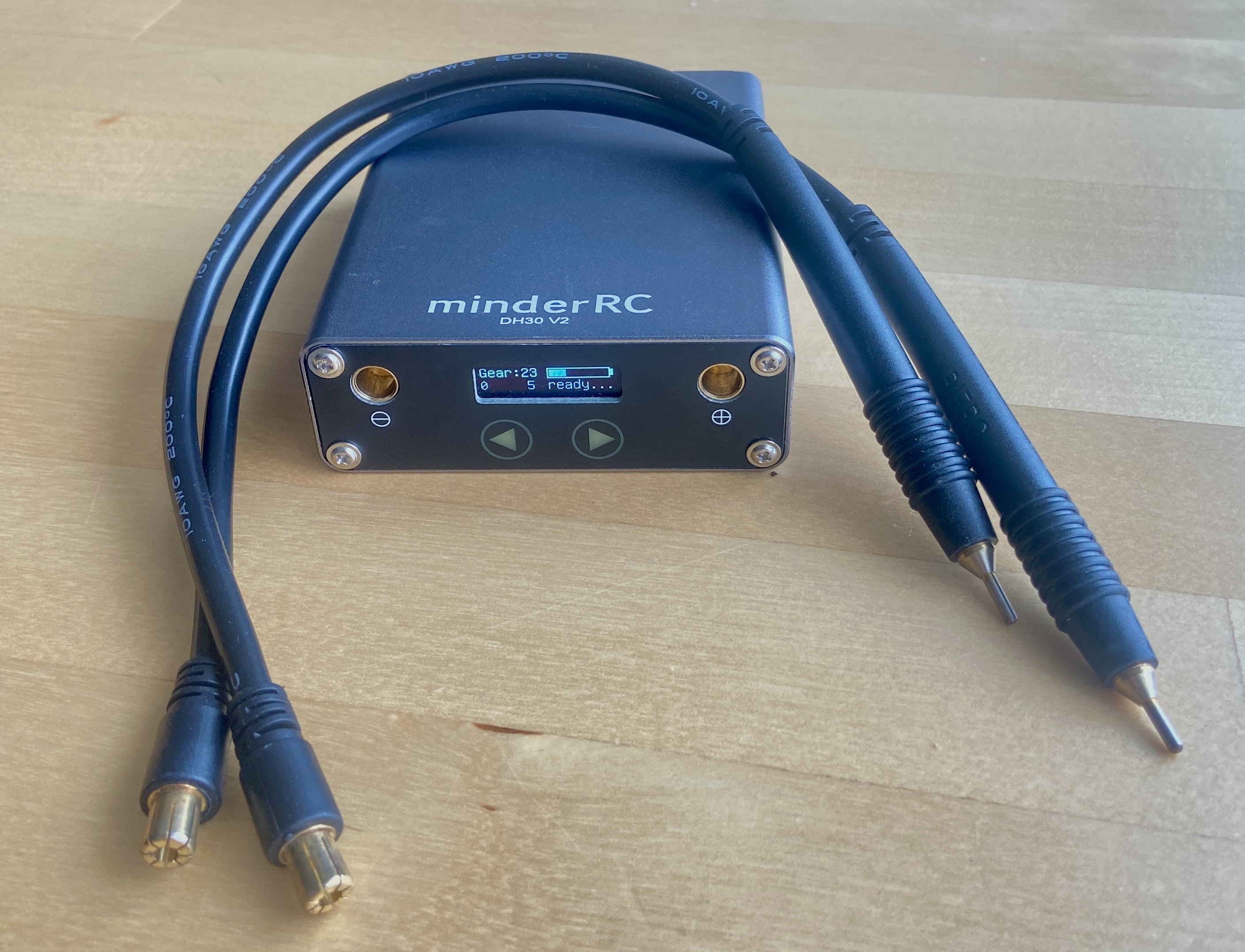
The spot welder gave me trouble while testing it out until I realized I was pushing the electrodes into the nickel strip with too much force. When the test welds would be too weak and the strip would break free, I would instinctively push the electrodes even harder into the strip with no success. Checking the manual, I found some vague guidance that the electrodes should only be pressed lightly into the strips while welding. Looking further into it, there needs to be some contact resistance between the strips in order for the welder to deliver enough energy into the "load" to melt the metal. If you press too hard with the electrodes, the contact resistance is too low for full energy transfer into the strips.
Once I had done enough successful test welds, I started on welding the cells. The first few steps were joining the parallel cells together into their groups and attaching the BMS wires to the appropriate terminals.
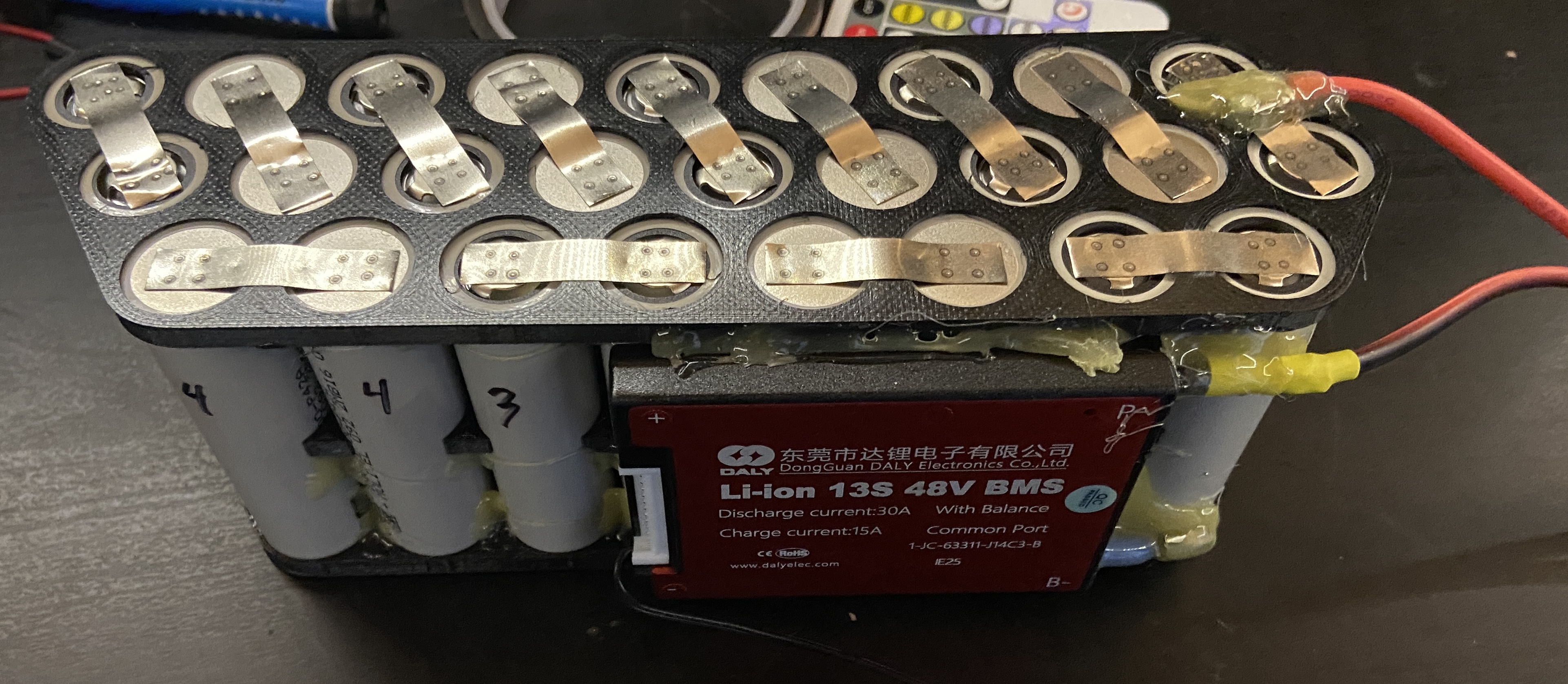
After this, the positive and negative terminals of the adjacent cell pairs needed to be connected with more spot welded strips. Extreme caution is needed at this point in the build to prevent any short circuits or mistaken connections, since the unprotected cells can deliver a lot of energy, especially as the series voltage increases.
The final bit of battery assembly requires a cell balancing wire to be connected from the BMS to each terminal junction of the 13 cell groups. I used a similar technique as I did with the BMS power wires, first soldering the wire to a small nickel strip, then spot welding the strip to appropriate terminal.
After all the electrical connections were completed, I carefully covered all terminals with electrically insulating "fish paper" before heat shrinking the whole battery pack.
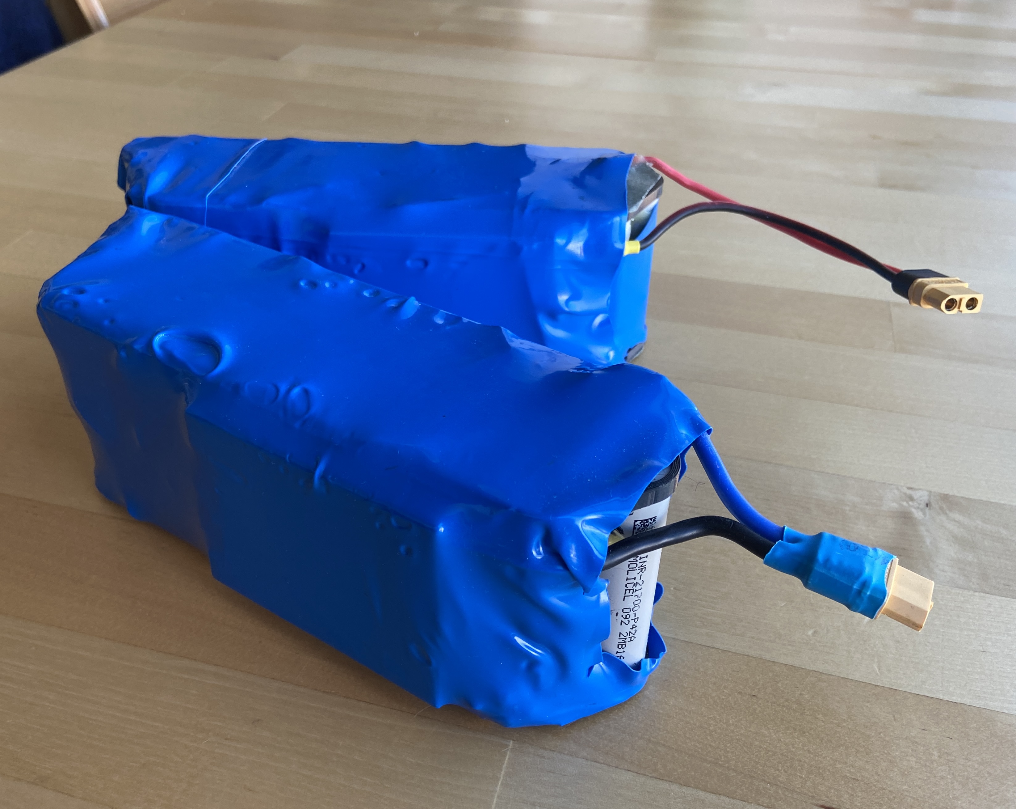
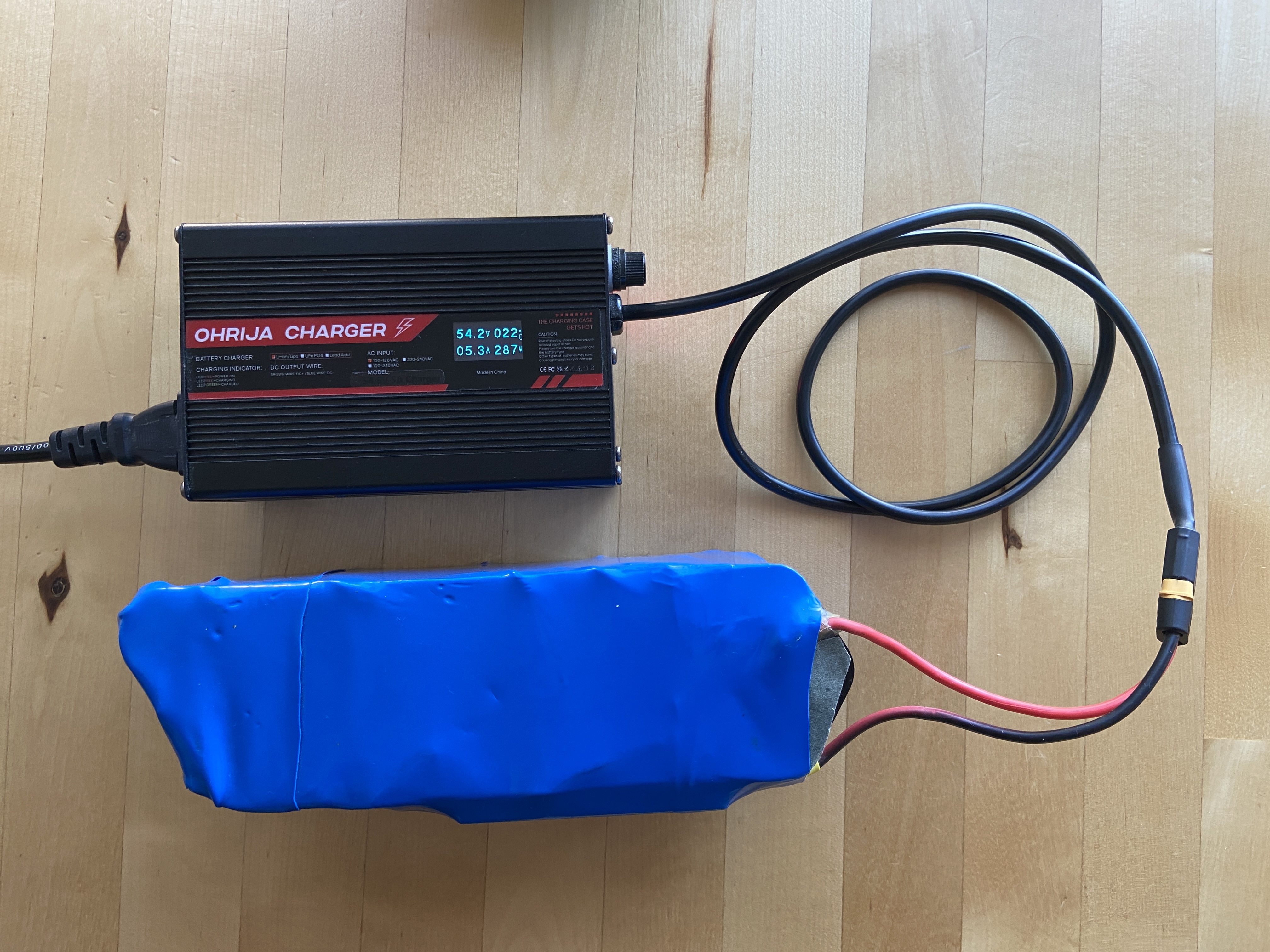
To charge the batteries I found a lithium ion battery charger for my 13S/54.6V configuration with an XT60 connector. The maximum charge current is 5A which is well within the specs for the Molicel P42A cells and the Daly BMS. The charger acts as a constant current/constant voltage charger, where the charger will adjust the charge voltage to charge the battery at a constant 5A until it reaches the maximum voltage of 54.6V for the 13S configuration.
The range has been perfect for my riding, using the throttle for pedal assistance rather than throttle alone.