Oliver Palmer
CNC Coffee Table
I found a coffee table someone had left on their curb for free while out with a friend one night. It was made for West Elm and seemed nice (was heavy), so we grabbed it figuring one of us would want it.
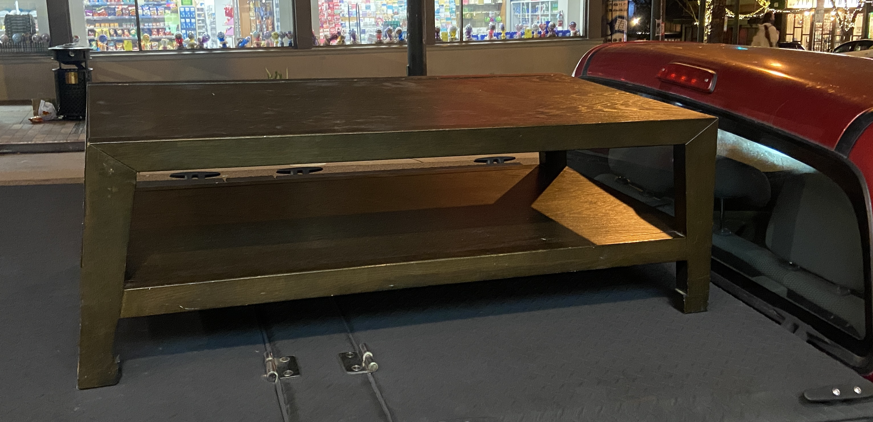
After the excitement of the find wore off, we each realized we were happy with what our current coffee tables provided and didn't want to make the switch to the new boat anchor table. It was taking up a good bit of space in my apartment so I was going to have to set it free or do something with it.
I was already thinking of building a CNC router around the same time; looking at the table, I thought it might work as a solid enough base to build off of. Most CNC projects in this smaller, ~2'x4' footprint seem to use aluminum extrusions for the frame, but it was hard to imagine the coffee table wasn't at least as rigid and sturdy as a simple aluminum frame I would have to put together. Plus this frame was free, and already built.
I took a while to decide how I was going to make a gantry, looking again at other similar projects for inspiration. The gantry would contain the x (side-to-side) and z (up-and-down) axes. It would need motors, guide rails, lead screws, limit switches, and mounting plates for each axis. Just like with the frame base, most of these DIY CNC builds use aluminum extrusions for the gantry structure.
At some point I stumbled upon a standalone gantry upgrade kit for the Genmitsu 4040 Pro router, advertising upgraded lead screws and guide rails, with a clamp mount for the size of palm router I was looking at using. The 400mm machine travel and ~2' overall width were conveniently the specs I was looking for, and so I purchased the standalone gantry for about $250.
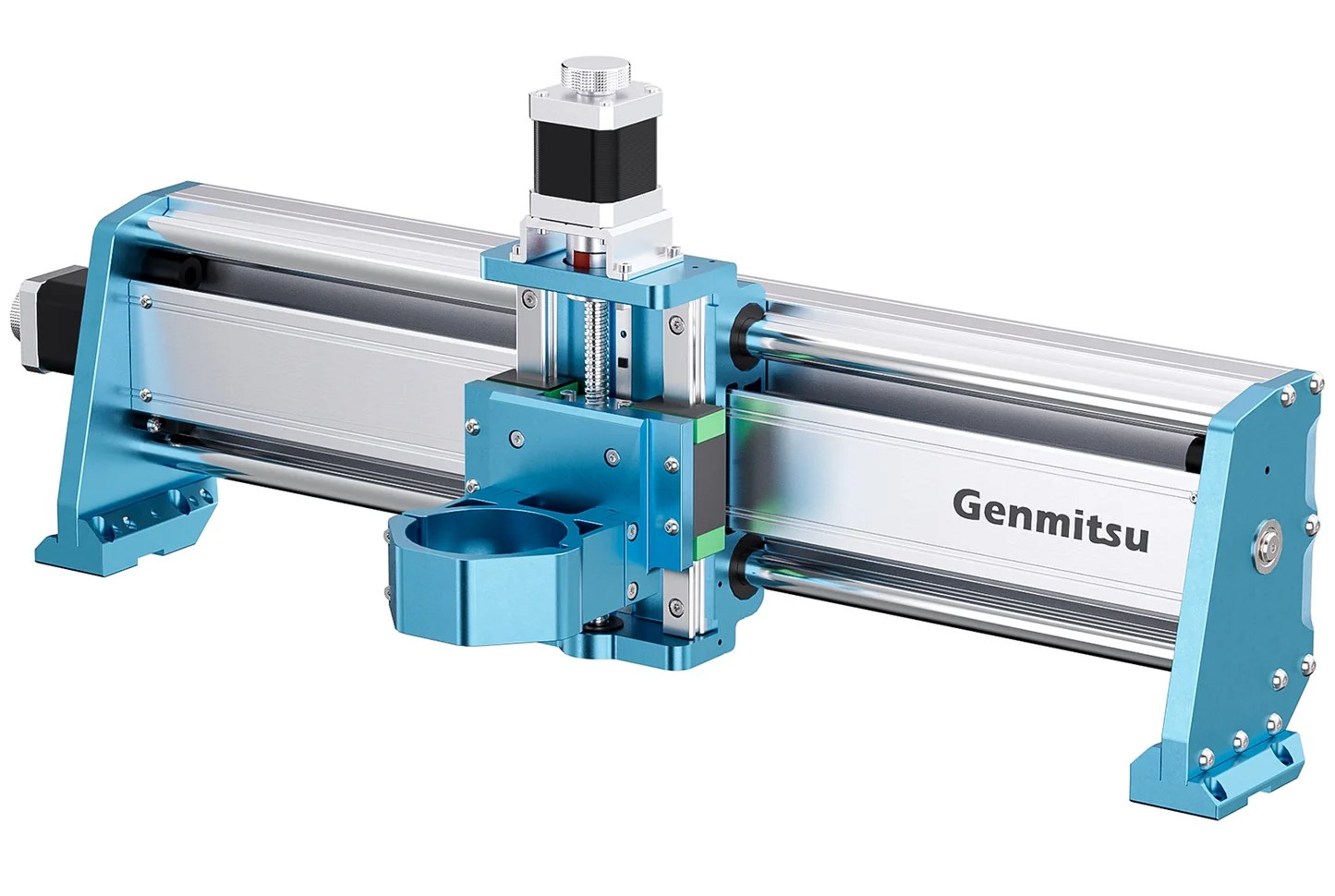
This was a great decision; there was no chance I could have built the gantry from parts for that low price and level of convenience. Plus, I was confident it could handle the level of wood and aluminum cutting I was looking to do since plenty of users have tested and shared its capabilities already.
With the gantry sorted, I could focus on just the y axis, spanning the length of the table. At this point I was still deciding on the level of investment I wanted to put into the project, weighing a cheaper SBR-style linear rail/belt drive setup against a more expensive but more rigid HGR-style linear rail/ball screw setup. I eventually went with the more robust option for the longer y axis, buying 2x 1000mm HGR20 linear rails and SFU1605 ball screws from Aliexpress for around $300. Having fully committed to the project with the y axis components, I picked up 2x NEMA 34 stepper motors with integrated drivers and a Carbide 3D brand router with an ER-11 collet.
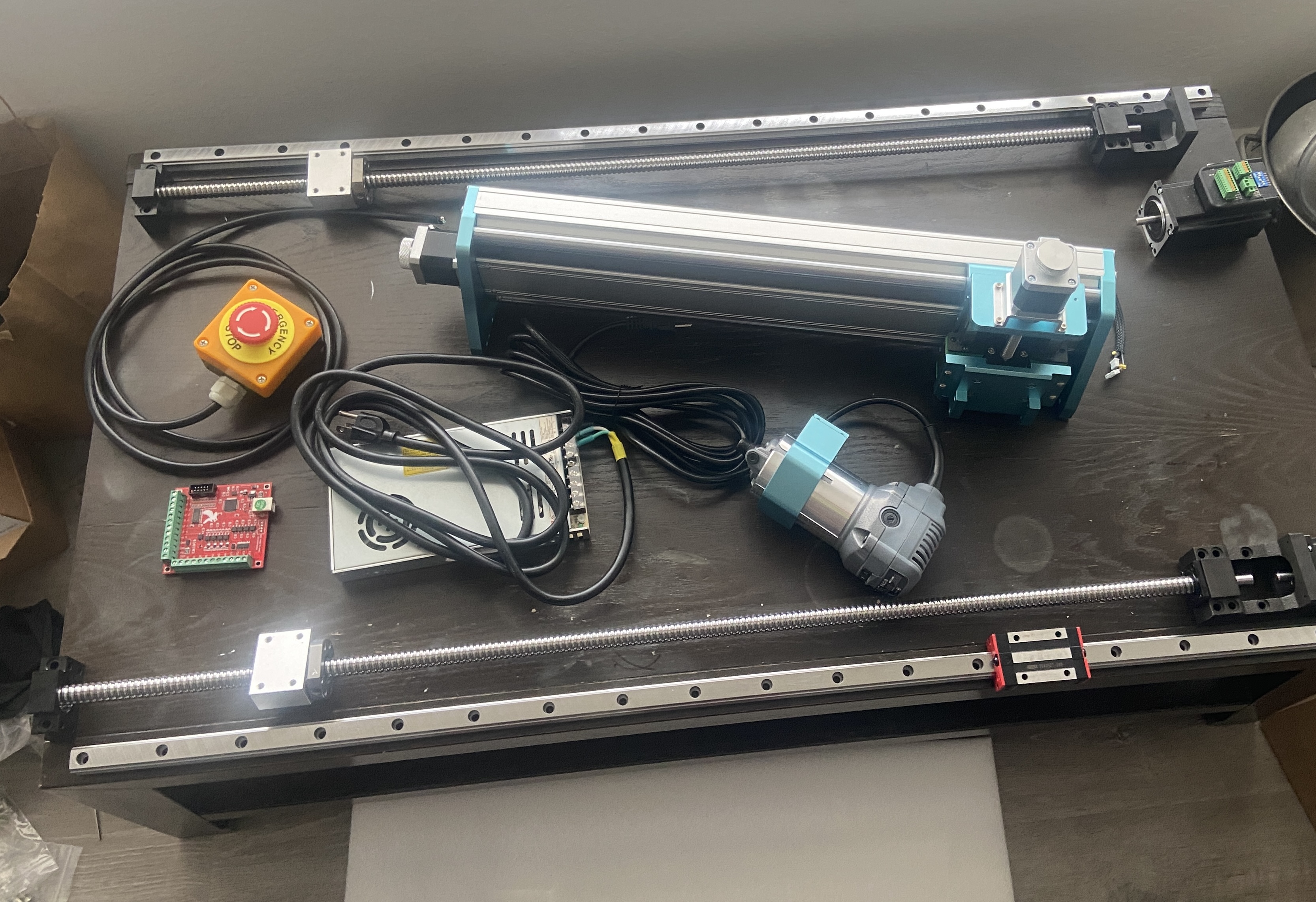
After I had received all the mechanical components, I needed to figure out how to package them all together. The rails could be easily mounted to the edge "leg" pieces of the table, but the ball screws needed to drive the gantry on the rails would interfere with the x axis work area if placed on the table. The work area could be reduced a few inches, setting software limits or perhaps adding spacers to bring the limit switch mounts in, but I would need to come up with some kind of baffled cover for the ball screws to keep them free of sawdust and metal chips. I decided that it would probably be possible to mount the ball screws on the sides of the table leg pieces, if I made a mounting plate for each of the end support blocks. The ball screw was just barely too short to be bolted directly to the sides of the legs, but a mounting plate could span the gap and hold everything together.
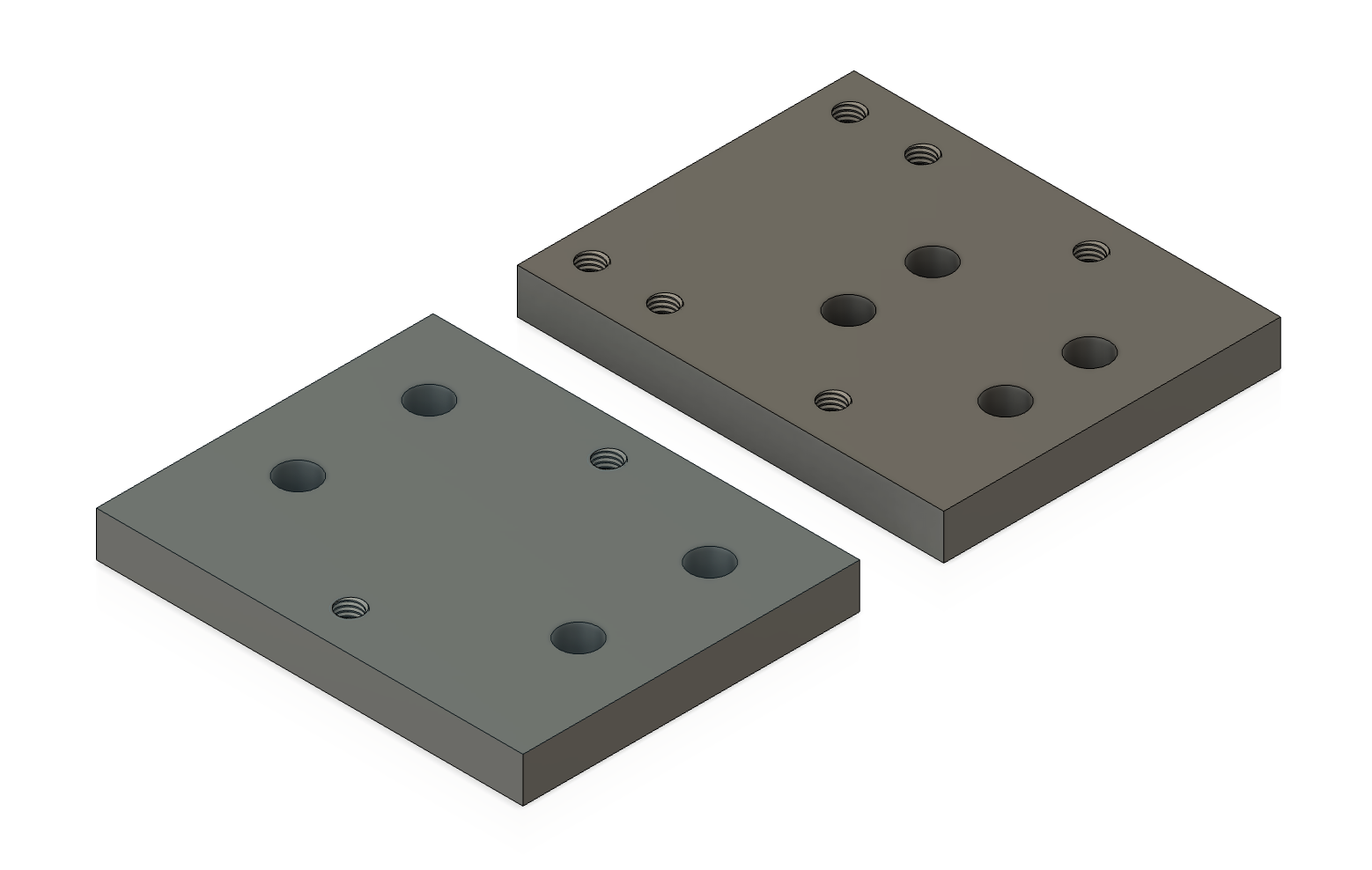
I designed a set of the plates for the two ball screw end blocks in Fusion360 and did some test 3D prints to make sure there was no issue with the mounting screw hole spacing. After this, I had to figure out the mounting of the gantry to the linear rail bearing blocks, and the connection of the gantry on rails to the motor driven ball screw nuts on either side. The gantry mounting feet had bolt holes, but the spacing didn't match up with the linear rail bearing blocks. On top of this, the gantry would have to be raised above the bed by 1 to 2 more inches to have an acceptable z axis clearance for the work pieces.
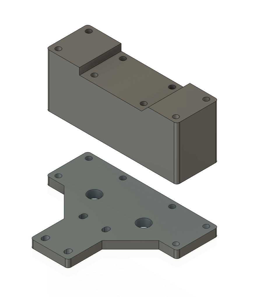
I broke the design into two pieces to solve this, using a 3D printable spacer block to elevate the gantry and a laser cuttable plate to translate the motion of the ball screw bearing to the gantry/linear bearing assembly. Since I was using two linear rail bearing blocks per rail, I could make up for the gantry mounting hole spacing mismatch by having the mounting footprint span the gap between the two bearing blocks. There was a further mismatch of the bolt hole spacing in the x axis direction, for which I just left oversized holes in the plate to fit a nut for the bolts.
I had the plates made in 8mm thick 6061 aluminum through SendCutSend, which came out to about $100 for all 6 parts with 16 total tapped holes. The ball screw end supports would be mounted to the plate with M6x1.0 screws, so the 8mm plate should provide enough thread engagement (1.3x diameter, 8 threads), though the threads being tapped aluminum might be slightly weak for this rule of thumb. While waiting for the SendCutSend parts to arrive, I began drilling and mounting the guide rails in my living room.
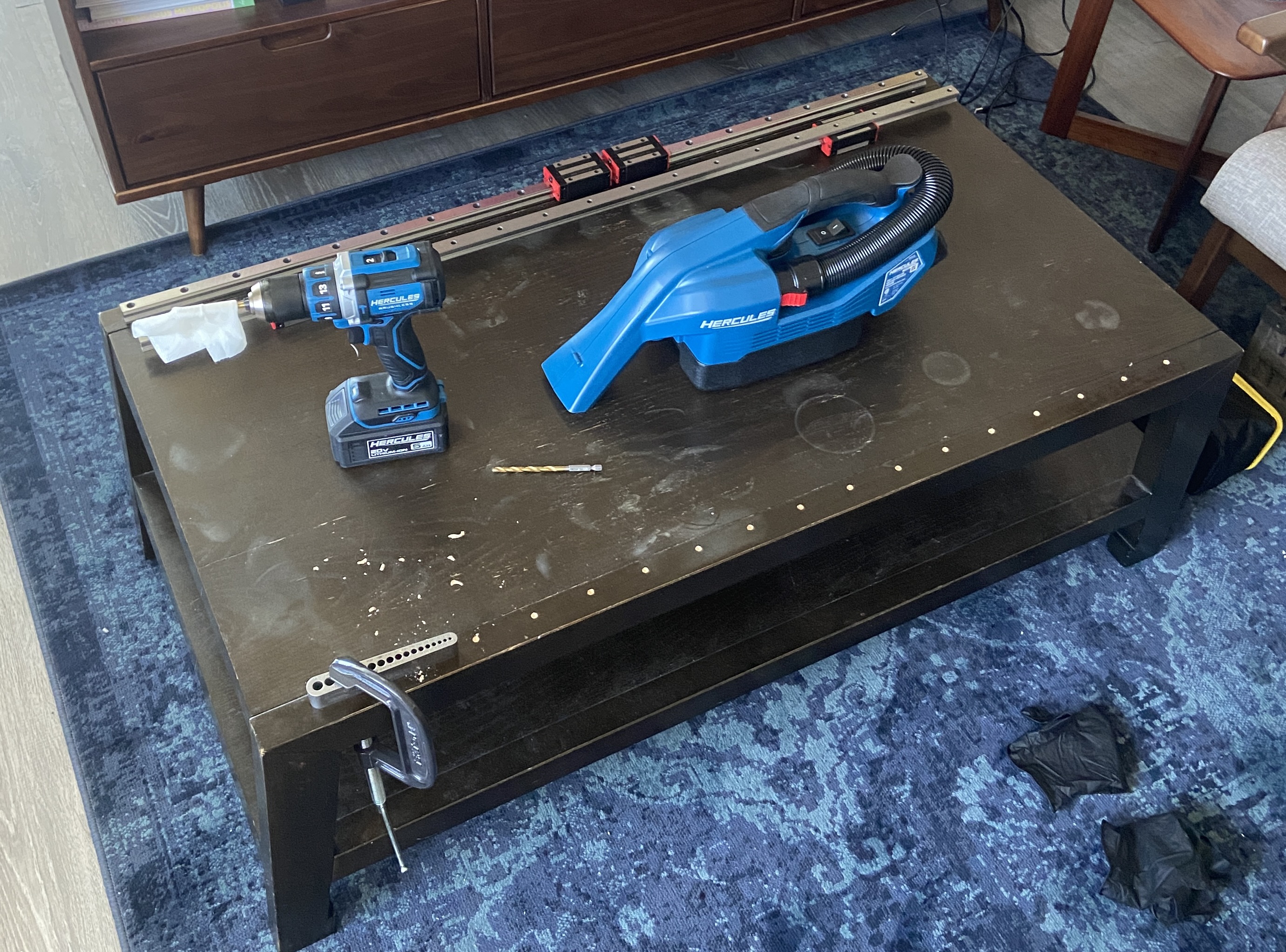
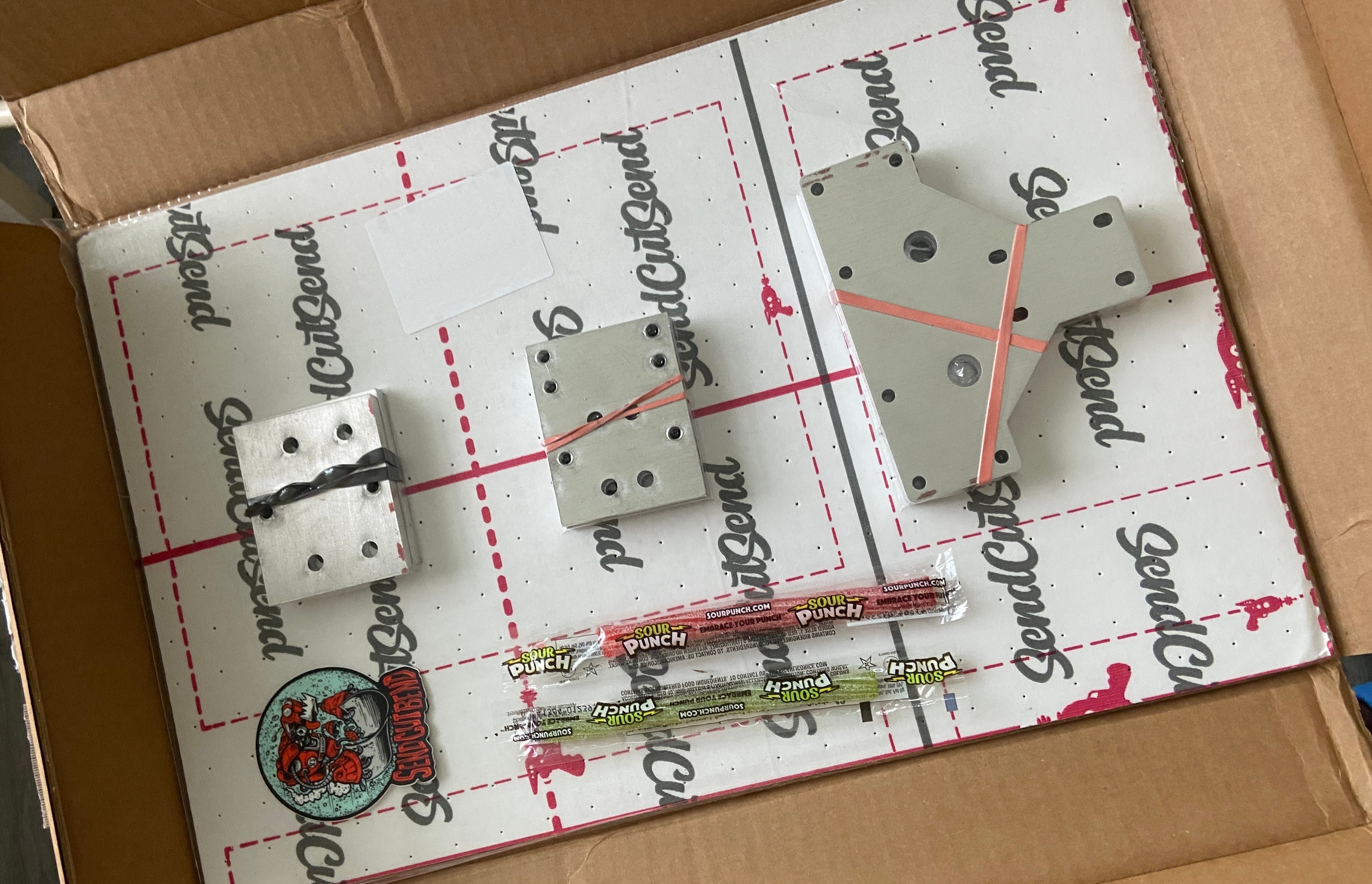
The parts arrived shortly, and I 3D printed the spacer blocks to begin the gantry assembly.
The gantry mount setup came together without a problem since I had already double checked the metal plate dimensions with a 3D printed test part.
At this point I was becoming more confident with the rigidity of the setup. The 3D printed spacers were just plastic, but they were in compression and held together by 8 M5 bolts. I decided I would trust that they were fine and if I needed them to be stiffer later on I would worry about that then.
Mounting the ball screws to the table sides went smoothly as well. I used 1/4" GRK Rigid Structural Screws to attach the mounting plates to the table, and M6 bolts for the ball screw supports to the mounting plates. To get complete thread engagement into the mounting plates, I drilled clearance holes in the table beneath the plate threads and used bolts long enough to pass through the entire plate.
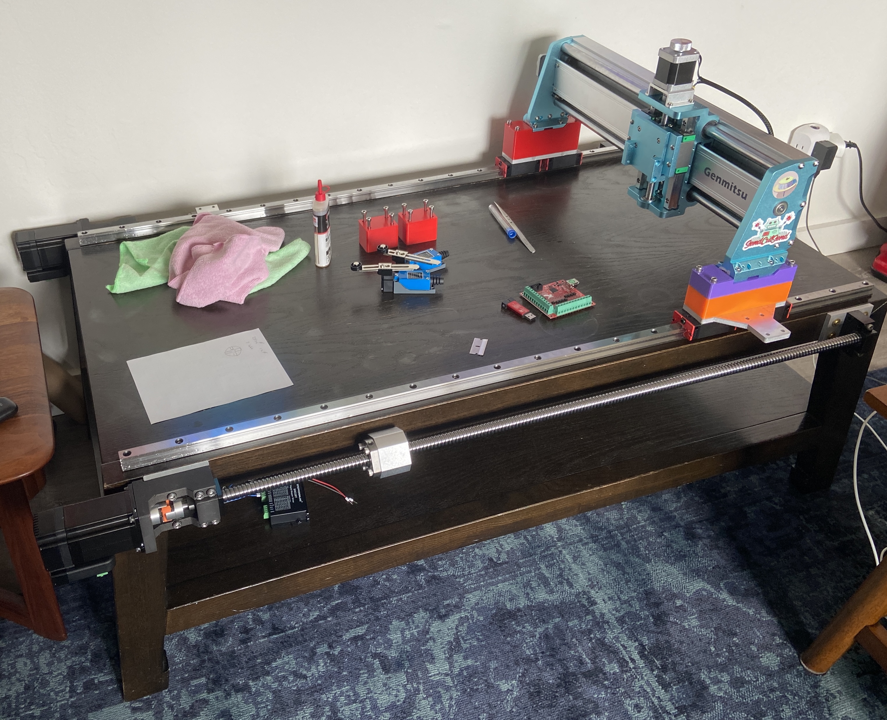
The connection of the ball screw nut to the gantry plate used a similar 3D printed spacer strategy as the gantry spacer, with long M5 bolts holding everything together. In the image above, these spacers are the red blocks, which are just ready to be installed.
With all the mechanical parts sorted, I needed to focus on the design of the electronics. I already had purchased the main components I needed: y axis motors with integrated drivers, limit switches for the y axis, motor drivers for the gantry x and z axis stepper motors, and the CNC motion controller board.
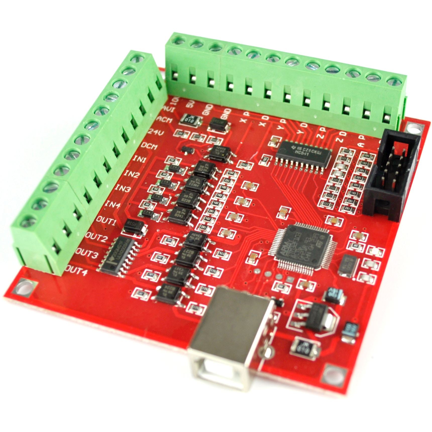
The board I eventually settled on was the BSMCE04U board. This board isn't manufactured and sold by any specific company as far as I can tell, you'll commonly see it listed as a "Mach3 Motion Control Card" sold alongside a CD with a cracked copy of the Mach3 CNC controller computer program. The board is cheap and fairly simple, with an STM32F1 mcu (or equivalent clone chip), USB interface, 8 optocoupled inputs and outputs, 4 axes worth of pulse and direction outputs for stepper motor drivers, and a pin header connector for a handheld "MPG" control pendant.
I didn't want to run Mach3 as my controller/G-Code sender (illegitimate or otherwise). I wanted to use the open source cncjs program, since it could run on a server and allow me to control the CNC router through a web interface on multiple devices. Like most of the open source DIY CNC programs, cncjs expects to interface with a motion controller running one of the more popular DIY CNC firmwares, such as GRBL. GRBL is an old motion control firmware tied to the Atmel Atmega 328 mcu, and it usually shows up in light duty plotters and engravers driven by an Arduino Uno. The GRBL firmware has been expanded for use with 32bit microcontrollers by the grblHAL project, which supports a variety of processors, including the STM32F1 series. On top of that, the BSMCE04U board has already been mapped, configured, and tested with the grblHAL firmware.
To set up the BSMCE04U board, I just needed to modify some header files in the grblHAL source code for my physical CNC configuration (mainly defining the y-axis as a dual "ganged" axis to sync the ball screw stepper motors on either side of the table). After compiling the code for the proper STM32F1 target in STM32CubeIDE, I soldered pin headers to the board programming pads and flashed the binary with an ST-Link V2 clone.
With the motion controller board programmed and the various motor control and limit switch wires connected, the CNC router could begin taking commands through the cncjs interface.
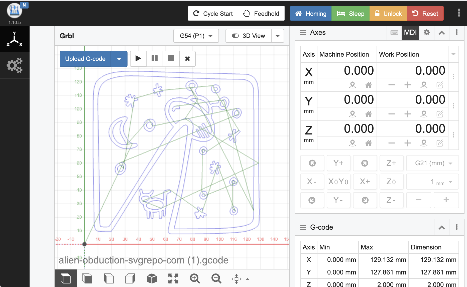
Needing to test the router inside, I attached a spring loaded pen to the router spindle to use it as a CNC plotter. I converted a test SVG to G-Code using the open source svg2gcode program, uploaded the G-Code through the cncjs interface, zeroed out the machine manually, and hit start.
Seeing the router finally produce something, even just a small pen sketch, was very rewarding. I ran the program again after re-zeroing the table 0.5mm in both the x and y directions to create the blurry effect in the picture.

After this, I used the CNC router as a plotter for two more projects, making a poster from part of an old map and decorating a bunch of cardboard bakery boxes to be used for holiday cookie box gifts.
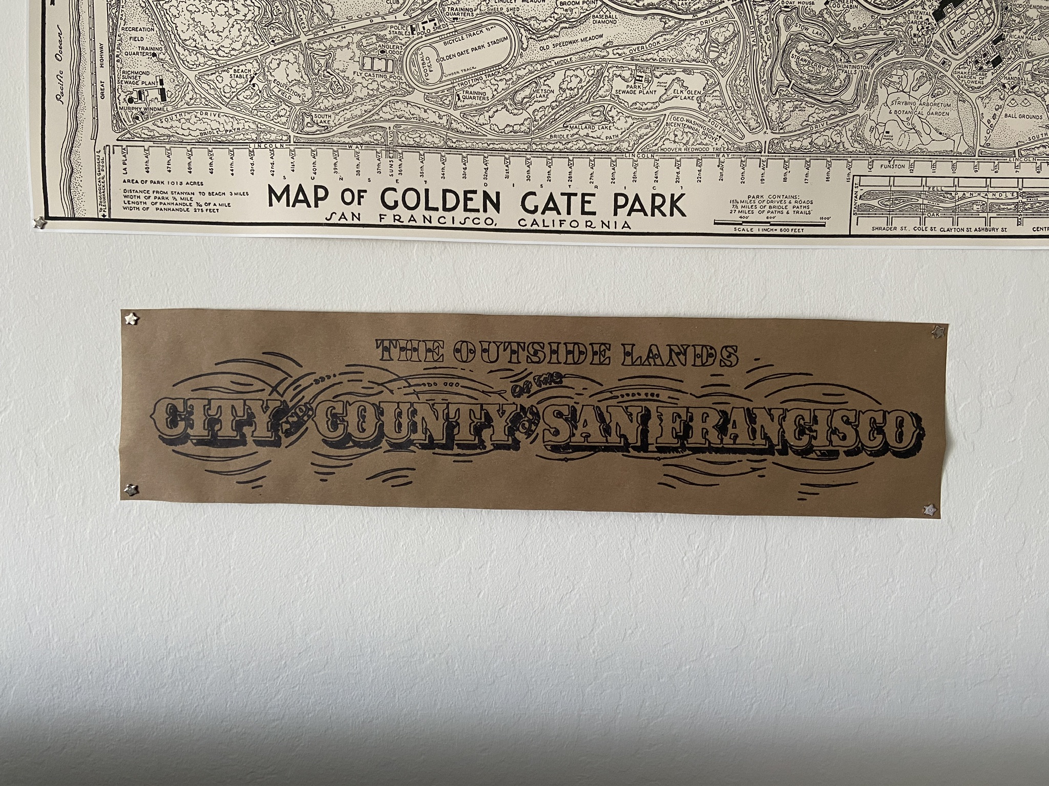
The map lettering was taken from an old hand drawn map of the Richmond and Sunset districts of San Francisco. I used Inkscape to crop and convert the bitmap lettering into vectors to be saved as an SVG. I had to abandon the first plotting attempt since the SVG (and G-Code produced from it) had the lines in an arbitrary order, causing the router to waste a ton of time jumping around the page to draw the next line. I found a solution in the vpype command line tool, which has utilities to sort SVG paths to minimize pen-up travel time and merge nearby paths within a given tolerance. This was perfect for the quick bitmap to vector conversion I had done earlier, and made for much quicker plotting the second time around.
Shortly after, I used the plotter capabilities to churn out a set of 15 or so holiday cookie box cover designs.
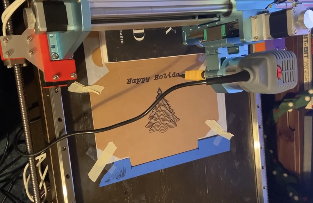
The tree on the box was generated from a user submission on the Turtletoy website, which is full of customizable, programmatically generated vector art based on the "turtle graphics" concept, which closely resembles the workings of a pen plotter moving around in two dimensions with the pen either down (drawing lines) or up (just traveling).
Currently, the CNC router project is in storage. It hasn't actually cut anything yet since I haven't had the space to set up an enclosure to catch sawdust and wood chips. I am hoping to revisit it sometime in 2026 to actually test the router capabilities.